You are here: Home / Measurements and Tests
Low Temperature Measuring Service

Measurement of Thermal Properties at Low Temperatures
Many physical properties of materials are temperature-dependent. Heat conduction, heat capacity and linear expansion in particular are temperature-dependent variables.
For the temperature range above room temperature, numerous values are available in the literature for almost all materials. Values are available for the temperature range below room temperature up to -197°C / -323°F (liquid nitrogen level), but not as detailed as above room temperature. There are hardly any precise values for temperatures below -197°C / -323°F.
Test set up for determining the thermal conductivity
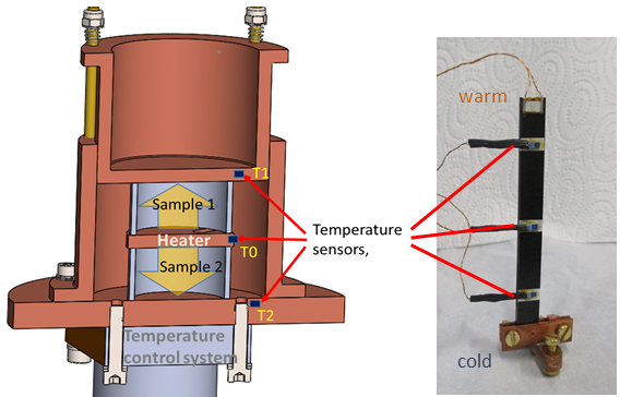
In order to be able to make reliable statements about heat conduction in selected materials in the cryogenic temperature range, a test rig for investigating thermal conductivity was set up at the ILK Dresden. The thermal conductivity \( \lambda \) of a material is defined as the heat flow \( \dot{Q} \) over a defined cross-section \( A \) and a length \( l \) at an externally imposed temperature difference \( \Delta T \). \begin{equation} \lambda = \frac{\dot{Q} \cdot l}{A \cdot \Delta T}\left[ \mathrm{\frac{W}{m\:K}} \right] \end{equation} Thermal conductivity can also be understood as thermal resistance. With the measuring principle used, a heat flow or heating power is specified and the temperature difference across the sample to be tested is measured. It must be ensured that the applied heat flow can only flow over the sample cross-section and not over the surrounding structure or atmosphere. To minimize these lateral influences, a symmetrical measurement setup can be selected, see Figure 1, left. The sample heater is located in the middle between two identical samples. Both samples are surrounded by a thermally conductive structure, the measuring cell. A defined heat output is applied with the heater. The resulting heat flow, yellow arrows, is transferred to the measuring cell via the two samples. The measurements are carried out in a stationary state and in a vacuum. With the aid of the temperature control system, these measurements can be carried out very precisely and fully automatically at different temperatures. For larger sample dimensions, simpler arrangements are also possible, see Figure 1, right.
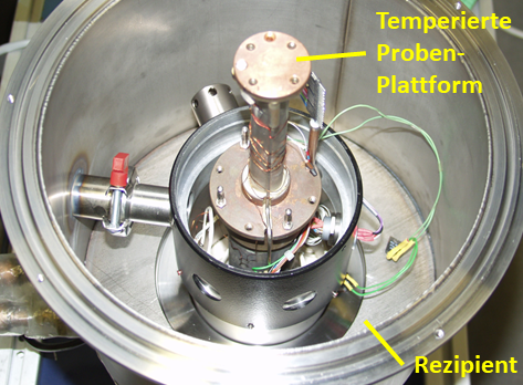
Several test setups are available for examining the samples. Figure 2 shows a set-up specifically for testing samples in shape of pipe sections. The height of the measuring cell used can be adjusted to different sample lengths and adaptations to other sample shapes are also possible. In other setups, rod-shaped samples or flat samples can also be examined.
| Sample Paremeter | Limits |
|---|---|
| Materials | plastics, metals |
Dimension: pipe section Da x L Dimension: flate sample L x B x H | 30 x 20 x 1 mm, 1.2" x ¾" 80 x 10 x 2 mm |
| Temperature range | 4 ... 333 K / -269 ... +60°C / -452 ... 140°F |
Test set up for heat capacity measurement
Like thermal conductivity, the heat capacity is a temperature-dependent physical quantity. The specific heat capacity of a substance measures the ability to store thermal energy and indicates how much energy is required to heat one kilogram of a certain substance by 1 K, for example. The specific heat capacity c can be determined using the heating pulse method. This involves heating a sample equipped with a heater and a temperature sensor for a defined period of time. The integral of the electrical heating power supplied over this period of time gives the amount of energy Q required to heat the sample with a mass m by the measured temperature difference \( \Delta T \). \begin{equation} c = \frac{Q}{m \cdot \Delta T} \left[ \mathrm{\frac{J}{kg\:K}} \right] \end{equation}.
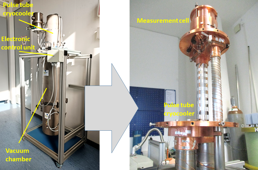
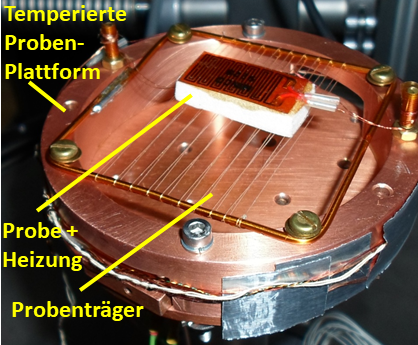
Figure 3 shows the test set-up, with the temperature control system with cryocooler and figure 4 the sample carrier with a sample and sample heater mounted on it on the right.
The sample carrier was specially designed to ensure minimal heat input into the sample. The measurements are carried out in a thermally stationary state and in an insulation vacuum lower than 1 x 10⁻⁴ mbar in combination with superinsulation foil to exclude heat flows from the environment into the sample. The heater and the temperature sensor also have their own heat capacities. These are determined in a separate test without the sample. The measured values of the sample are in turn corrected with these components.
| Parameter | Limits |
|---|---|
| Materials | plastics, metals |
| Dimensions, L x W x H | 30 x 30 x 10 mm, 1.2" x 1.2" x 0.4" |
| Temperature range | 20 ... 333 K / -253 ... +60°C / -452 ... 140°F < 20 K on request |
Test set up for determining the thermal expansion
Starting from a reference temperature \( T_0 \) and a length \( L_0 \) materials change their geometric dimensions when the temperature changes. Most materials expand when heated and shrink when cooled. The physical characteristic value for this behaviour is the temperature-dependent and material-specific coefficient of thermal expansion \( CTE \) or \( \alpha(T) \). \begin{equation} \alpha(T) = \frac{dL(T)}{dT} \cdot \frac{1}{L_0} \left[ \mathrm{K^{-1}} \right]\end{equation} The samples are cooled using a cryocooler. The sample temperature is then changed within a specified range. The temperature is controlled using an electric heater on the sample holder. The change in length of the sample and the temperatures at both ends of the sample are measured discretely over time. The expansion coefficient \( \alpha(T) \) is calculated from these variables for each temperature step.
The samples are clamped on one side of a sample holder, see figure 6, and mounted in the experimental setup. The sample holder is thermally and vibrationally decoupled from the cryocooler. The samples are surrounded by a thermal shield to reduce heating by thermal radiation and thus temperature gradients in the samples. In the case of materials with poor thermal conductivity, such as plastics, this gradient is much more pronounced than with metallic samples. To reduce this gradient, a thermally conductive exchange gas is also used in the sample chamber. The free ends of the samples are scanned through the optical window using a laser measuring system, a triangulation measuring system. The measured values of sample length, temperatures and measuring time are recorded by the PC and then evaluated. Figure 7 shows the test stand and the laser measurement system in front of the optical window.
| Parameter | Limits |
|---|---|
| Materials | plastics, metals |
| Dimension, L x W x H | 100 x 10 x 2 mm / 4" x 0.4" x 0.08" |
| Temperatur range | 20 ... 333 K / -253 ... +60°C / -423°F ... 140°F |
| Amount of samples | 2 samples, 1 reference |


