You are here: Home / Measurements and Tests
Air-flow test rig for fan characteristic measurement

Flow test rig according ISO 5801
ILK Dresden has designed various test rigs in order to evaluate the performance characteristics of fans. These are designed and manufactured specifically for the requirements for fan development and to optimize current products. The test rig has a particularly high measuring accuracy and reproducible measurement results.

Flow measurement
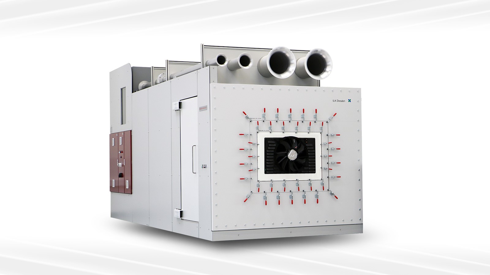
The chamber test rig, shown in the picture, fully meets these requirements and complies with the conditions, standards and guidelines of the following:
- ISO 5801: 2017
- EU-Regulation 327/2011
- prEN 17166: 2017
The measurement of the volume flow is carried out using orifice plates according to ISO 5167-2. Four different orifice plates allow a large volume flow measurement range of 0.003-7 m³/s (11-25.000 m³/h) with high measuring accuracy. The switchover of the measurement ranges is software-based. The length of the pipe inlet, as seen in the picture, guarantees a disturbance-free pipe flow, as this is the basic requirement for high measuring accuracy. For the design of the measuring sections, a maximum possible measuring range and a high measuring accuracy is of great importance. The resulting drop in pressure is compensated by an auxiliary fan located behind the flow measurement device. The auxiliary fan has a radial design, is speed-controlled and permits the stable setting of the desired operating conditions.
Setup of the Flow test Rig
Test chamber
To set the pressure on the suction side of the test fan, the required airflow is fed into the measuring chamber via the diffuser and a motor-driven throttle flap. A system of rectifiers and screens in the measuring chamber ensures an evenly distributed, axially, parallel inflow to the test fan. The high demands on the flow in the measuring chamber are necessary to prevent disturbing influences on the characteristic curve behavior of the fan and static pressure measurement. When designing the size of the intake chamber, space was provided for additional parts. This allows to simulate specific installation situations and to determine their effect on the characteristic curve behavior of the fans. In addition, the test chamber has a door supporting easy modifications or installations on the suction side of the test fan.
Software ILK-FlowMeas
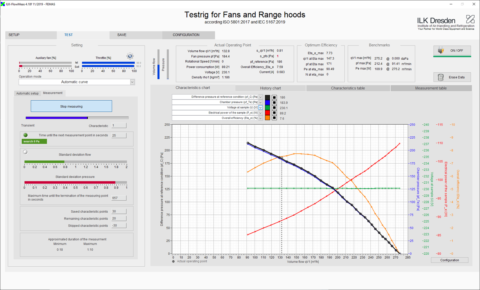
The operation of the test rig is especially suitable for measurements in the field of development and product testing via a very comfortable PC software. The parameters required for determining the characteristic curve (volume flow rate, based on the state variables in the test chamber) the standard conditions are calculated from the measured values and displayed on the screen. The software ILK-FlowMeas³ can be used for fully automated measurement of characteristic curves as well as the display and storage of a characteristic curve or manually controlled set points. The operator has all the options to change and save the parameters necessary for the tests at their discretion.

Measurement report and data files
The measurement data is stored in an open data format. This allows processing the measurement data easily or to open it directly in Excel. Additional files relevant for the documentation of the test are stored in the same folder with a unique identification number. These include, e. g., a report, a software-based picture of the installation and a characteristic diagram. Alternatively, the metadata of the measurement or the measurement data can be stored in a database.
Measurement accuracy
The error estimation results with the selected sensors in a maximum measurement deviation related to the respective measured value for the volume flow of less than 1% and for pressure differences of less than 0.5% related to the respective measured values.
Application area of the fan test rig
The air performance test rig was especially developed for R & D for fan manufacturers.
Range of services
ILK-Dresden develops and manufactures test rigs as per customer order, which are adapted to suit the individual requirements. The comprehensive cooperation between specialist areas of materials technology, air-conditioning, energy and refrigeration technology and measurement and control technology guarantees our customers an optimal solution. In recent years, we have equipped numerous fan manufacturers and test laboratories with our high-quality volume flow test rigs.
We also carry out measurements on our own fan test rigs. ILK Dresden is accredited as a test laboratory for the measurements of fans according to ISO 5801 by DAkkS (German national accreditation body) according to ISO/IEC 17025. For detailed information, please do not hesitate to contact us at the above-mentioned telephone number.


