


You are here: Home / Measurements and Tests
Investigation according to DIN EN ISO 14903

These tests according to DIN EN ISO 14903 are possible at ILK Dresden
§7.4 Tightness Test
§7.6 Pressure- Temperature- Vibration Test
§7.7 Simulation Operating
§7.8 Freezing Test
§7.9 Pressure Test
§7.10 Vacuum Test
§7.11 Compatibility Test
§7.12 Fatigue Test
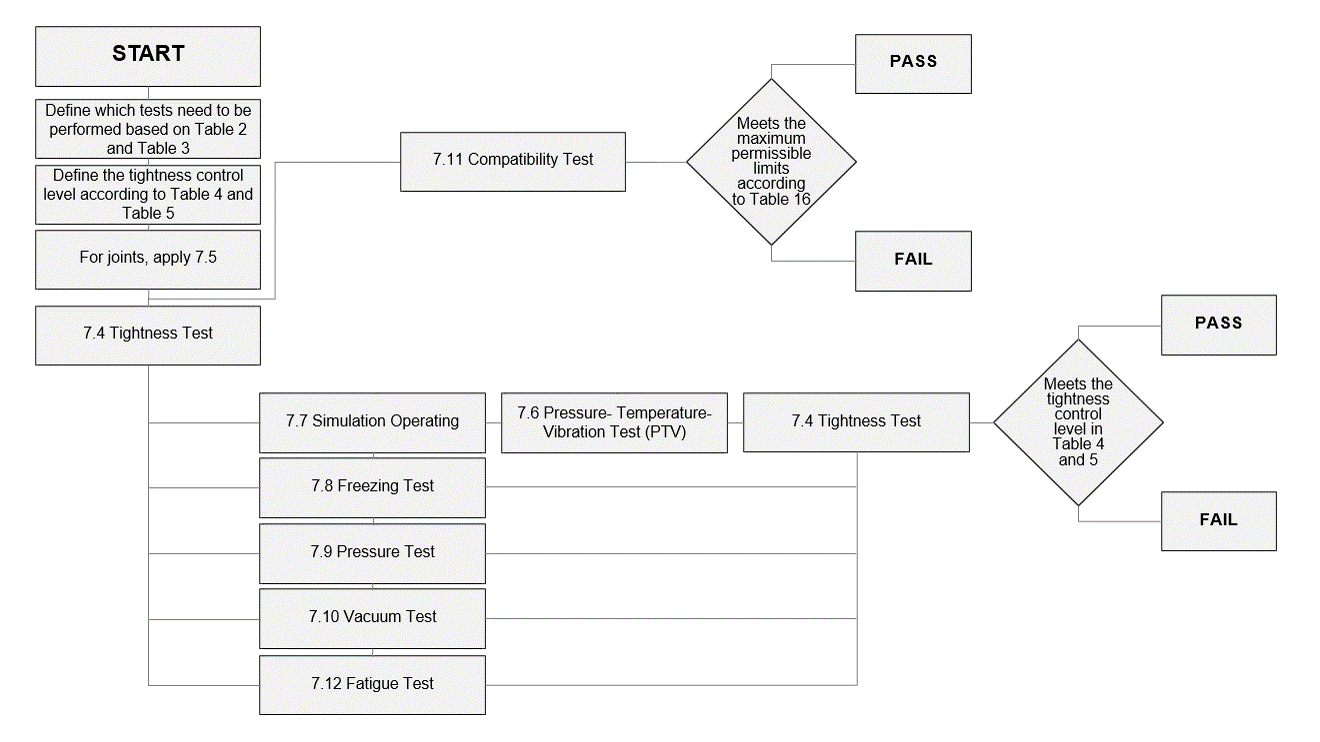
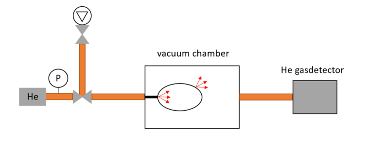
§7.4 Tightness Test
- Tightness control according to classification in DIN EN ISO 14903 at room temperature
- In each case per connection or component (test sample) before and after the respective modules
-
Permissible leakage rate (helium) depending on the selected tightness control level E.g. A1 with Q ≤ 7,5E-7 Pa m³/s = 7,5E-6 mbar l/s @ 10 bar rel., 20 °C
-
Testing with helium gas detector in vacuum method or substitute method
-
Procedure section 10 according to DIN EN 13185, Detection limit 5,0E-13 Pa m³/s helium
-
Test gas helium
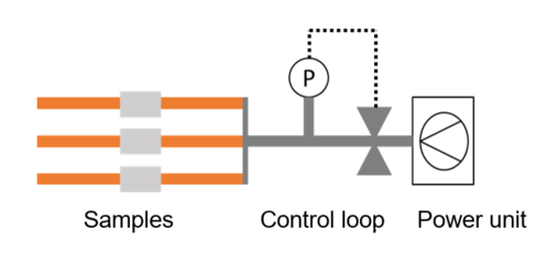
§7.6 PTV Test and if necessary §7.7 Simulation Operating
- Tmin: -40 °C (specified by the customer)
- Tmax: +140 °C (specified by the customer)
- Test pressure PSmax: 100 bar rel. (specified by the customer)
- 50 Temperature changes
- 200 Pressure pulses
- Subsequent vibration test < 200 Hz, 1 Axis, 2 Mio vibrations, const. amplitude
- Simulation Operating, E.g. 25x open and close the connection
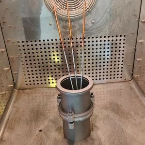
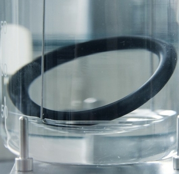
§7.8 Freezing Test
-
Freezing test in a vacuum test chamber. The test specimen is exposed in a vacuum chamber filled with water at 500 mbar abs (+ 0, -100 mbar) for at least 10 min. The pressure is then increased to atmospheric pressure.
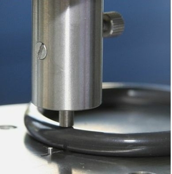
-
Afterward, the test specimens are stored at -15 °C (or below) for at least 30 min in a temperature-controlled cabinet and then exposed to water at ambient temperature for at least 5 min., these steps are repeated a total of 30 times
§7.9 Pressure Test
- The pressure test is performed at 5xPS for 1 minute
- Medium oil
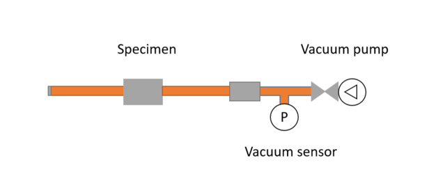
§7.10 Vacuum Test
- The test samples are subjected to the test to confirm that they are able to withstand a vacuum with an absolute pressure of 6.5 kPa for 1 h without leakage.
- For this purpose, the pressure is monitored and it is checked whether the pressure increase Δp after 1 h is less than 0.2 kPa. The effect of the temperature change on the pressure is taken into account.
§7.11 Compatibility Test
-
Investigation into the chemical compatibility of the materials
-
Aging for 336 h at 50 °C in refrigerant-oil atmosphere (for elastomer materials)
-
Aging for 1000 h at 50 °C in refrigerant-oil atmosphere (for thermoplastic materials)
-
Determination of mass, volume and hardness before and after aging
§7.12 Fatigue Test
-
Fatigue test, 250.000 Pressure cycles at max. 50 changes per minute
-
Test range between test pressure PS and atmospheric pressure, test medium: water
Your Request
Further Projects - Measurements and Tests

Tribological investigations of oil-refrigerant-material-systems
Modified Almen-Wieland wear testing machine

Investigation of materials
Investigations regarding the compatibility of materials with refrigerants, oils and heat transfer fluids

