


You are here: Home / Research and Development
Calibration leak for the water bath leak test
Kali.f.WaDi
Problem
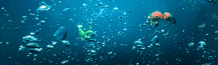
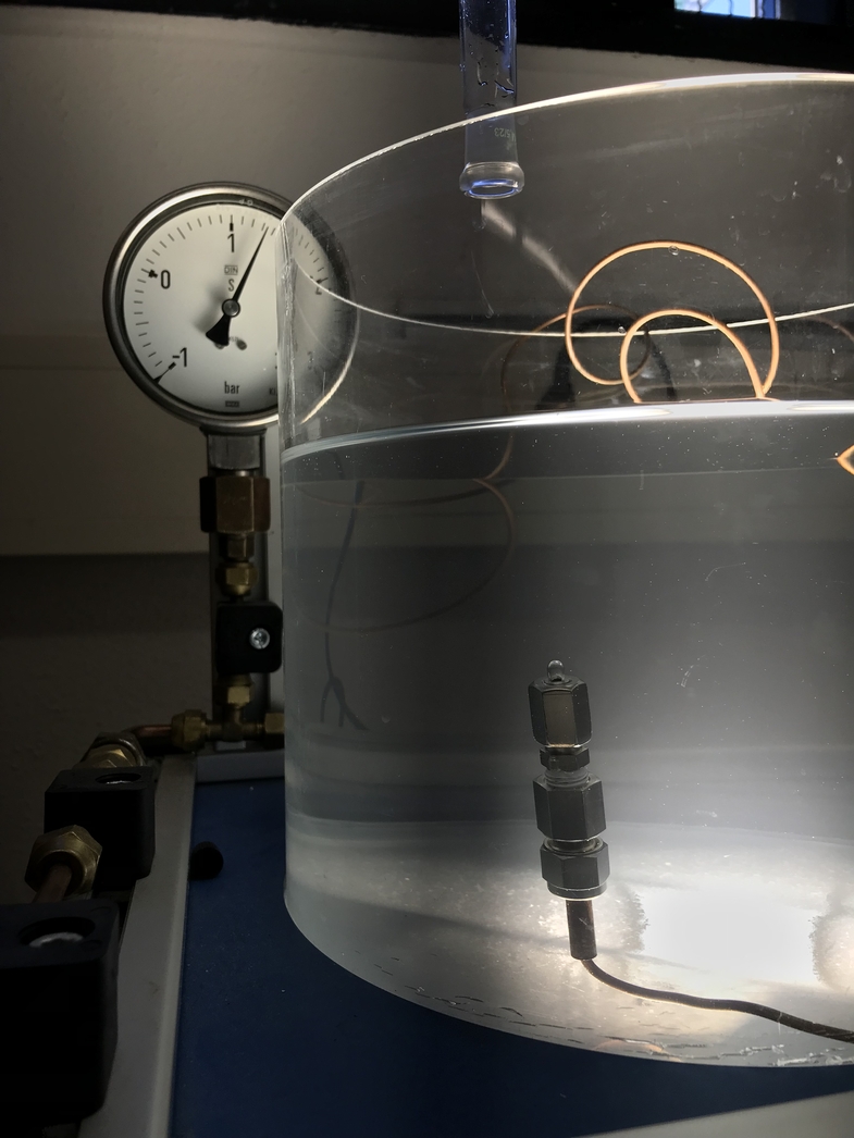
Various methods are available for leak testing of technical components, especially in refrigeration technology. These include the "bubble detection (immersion)" method (method C1 according to DIN EN 1779), which is widely used in practice. In this method, the test specimen is pressurized with test gas and placed in a basin filled with a test fluid (usually water with additives). Bubbles rising from the leak indicate the leak. This principle is generally known from its use, for example, for leak detection on bicycle inner tubes.
Under optimum conditions, leakage rates of 5 g/a refrigerant can thus be reliably detected. This makes the method suitable for use in refrigeration technology, whose permissible leakage rate is 5 g/a refrigerant (≙ 3x10⁻⁵ mbar l/s R1234yf) per connection point.
While a calibration option or at least a functional check is available for almost every technical process (for example, there are various calibration leaks for selective gas sensors on the market), this has not been the case for water bath testing to date. The calibration leaks available on the market to date are not suitable for underwater use.
However, the proof of test process suitability for leak testing by means of water bath testing, which is necessary from a quality management point of view, is hardly possible without a suitable reference or calibration leak.
State of the art
Although the water bath testing method is widely used in the market, no calibration leaks, especially with a leakage rate of < 10-3 mbar l/s, are available in practice as test standards for use in water bath testing. This applies regardless of whether the procedure is used manually or automatically. The leaks available on the market to date may not be immersed or submerged due to their design.
This gap in the market is to be closed within the scope of the project applied for by developing a corresponding calibration leak suitable for water bath testing.
Target
The project goal is to develop calibration leaks for the range of small leakage rates of 5 to 500 g/a refrigerant (corresponding to a leakage rate of approx. 3x10⁻⁵ to 3x10⁻³ mbar l/s R1234yf), i.e. (almost) to the lower detection limit of the water bath test. Converted to air, this corresponds to a volume flow of the order of 0.1 to 10 ml/h (assuming laminar flow).
For the broadest possible applicability, leaks with a predefined, fixed leak rate as well as leaks with a variable leak rate are to be developed.
Result
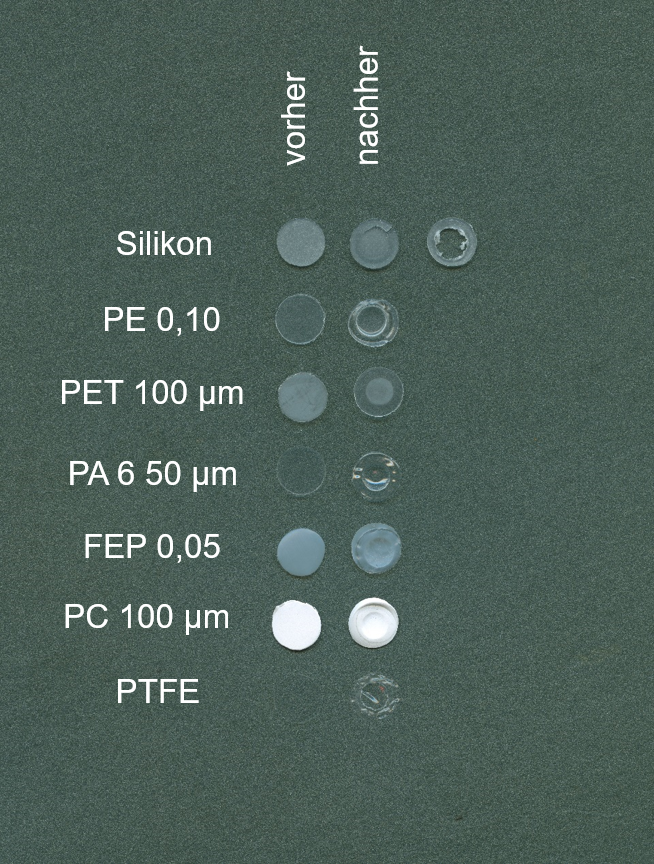
The possibilities of leak generation via membranes, perforated disks and capillaries were investigated. For this purpose, different membranes were examined for their suitability and different types and materials for capillaries and perforated disks for their suitability and magnitude of leakage rates.
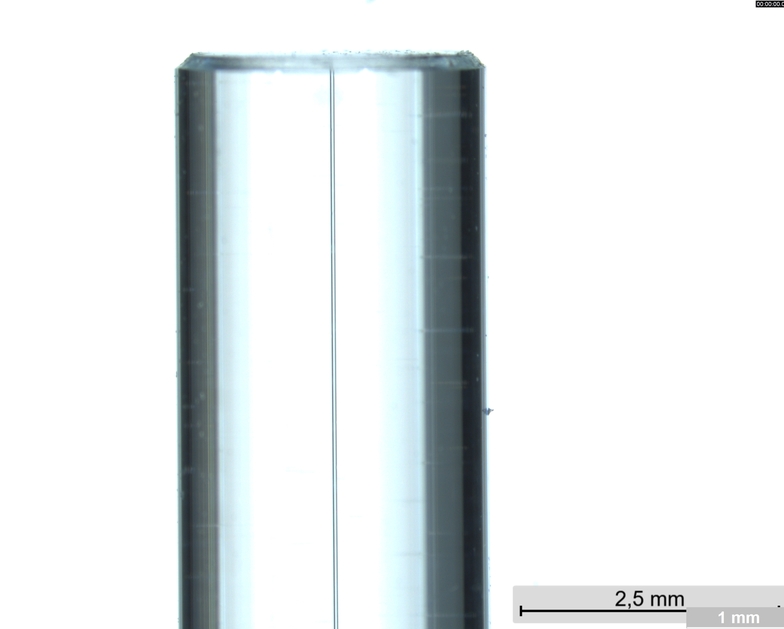
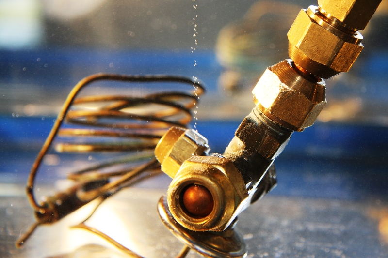
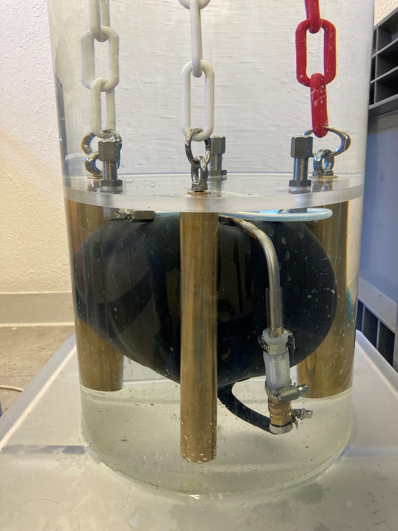
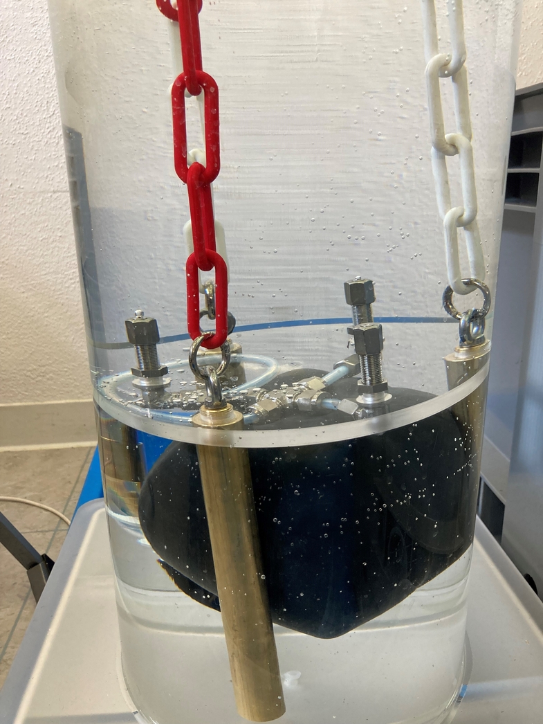
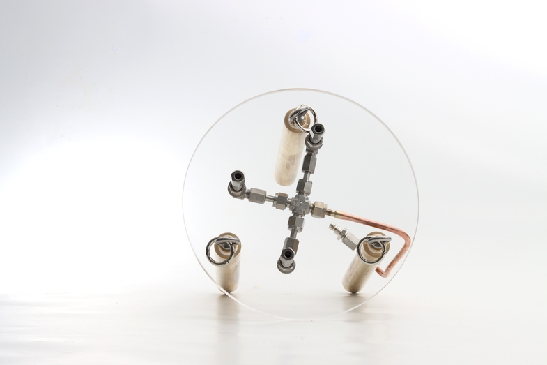
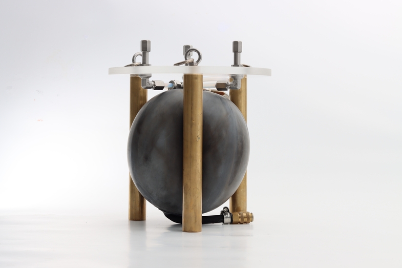
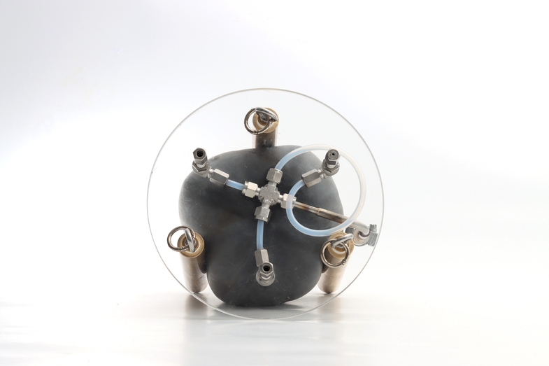
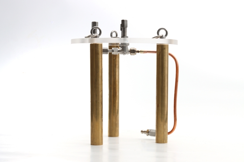
In order to achieve a stable leakage rate of the desired size, capillaries proved to be the preferred option. Various setups were then investigated and evaluated in a constructed water column. A gas reservoir in a flexible casing is particularly suitable for making the immersion depth of the leaks independent of the leakage rate. Several capillary diameters and lengths were investigated in order to cover the widest possible range of leakage rates.
These leakage rates can be realized with the examined capillaries and are constant for a period of approx. 0.5 to 3 hours, depending on the leakage rate.
Table 1: Experimentally determined leakage rates with forming gas as test gas
Leakage rate [mbar l/s] | Capillary size [µm] | |||
20 | 30 | 50 | ||
Capillary length [mm] | 10 | 1.2E-04 | 5.8E-04 | 4.5E-03 |
15 | 7.7E-05 | 3.9E-04 | 3.0E-03 | |
20 | 5.8E-05 | 2.9E-04 | 2.3E-03 | |
25 | 4.6E-05 | 2.3E-04 | 1.8E-03 | |
30 | 3,8E-05 | 1,9E-04 | 1,5E-03 | |
35 | 3,3E-05 | 1,7E-04 | 1,3E-03 | |
40 | 2,9E-05 | 1,5E-04 | 1,1E-03 | |
45 | 2,6E-05 | 1,3E-04 | 1,0E-03 | |
50 | 2,3E-05 | 1,2E-04 | 9,0E-04 | |
The leakage rates correspond to a volume flow of approx. 0.002 ml/min to approx. 0.3 ml/min (forming gas) or a leakage rate of approx. 5 g/a to approx. 1 kg/a R1234yf. The leakage range can therefore be used for different components or different requirements for the tightness of components and the testing of the leak test technology or the persons carrying out the tests.
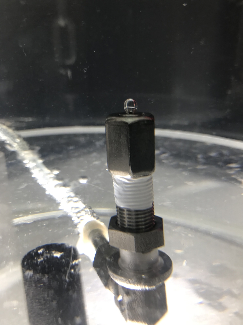
Various test leaks can currently be used as samples and are offered to customers for testing. The dimensions of the samples are Ø 220 mm x 220 mm and can still be changed according to customer requirements.
Your Request

Further Projects - Research and Development

All-in-one device for freeze-drying and production of biomaterial
with automated freezing and sterilisation option


Characterisation of Superconductors in Hydrogen Atmosphere
Are superconductors really compatible with hydrogen?