-water heat pump")


You are here: / Home
Innovative small helium liquefier

Liquefaction rates from 10 to 15 l/h
The goal of the R & D project is to explore new innovative ways to develop the functional model of a "helium liquefier for the small liquefaction rate". The development of such a system should cover the still non-existent area of the market.
This liquefier should contain several innovations and technical solutions:
- Development of a helium liquefaction system with a liquefaction rate of 10 - 15 liters per hour of liquid helium.
- Development of an innovative pre-cooling stage, which works with a mixture of helium and refrigerants as working fluid.
- Detailed investigation of an innovative helium cycle within the development of the helium small liquefier with the ability to operate in different operating regimes: helium liquefaction, cooling and temperature stabilization/control.
- Operation of the condenser with a liquefaction rate that can be varied over a wide range - between 75% and 100%.
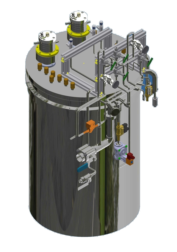
Currently, the functional design of the helium small liquefier is being set up. The figure shows a 3D model of the cold box, in which all heat exchangers and cold valves are mounted. In the upper part of the cold box, two prototypes of low flow helium turboexpanders are mounted. All external components, piping and condenser control system are located on the front of the cold box.
Your Request